| 2.3. Adjusting project properties | ||
|---|---|---|
| Chapter 2. BlueWhaleProcessing Project structure | | |
| 2.3. Adjusting project properties | ||
|---|---|---|
| Chapter 2. BlueWhaleProcessing Project structure | | |
Various aspects of the BlueWhaleProcessing project behavior can be controlled from a complex Project Properties dialog. There are several ways how to open the Project Properties dialog:
Select "Project properties" item from the project's context menu
Click on
 Project properties icon at the toolbar when any item in the project node
tree is selected in the Projects window
Project properties icon at the toolbar when any item in the project node
tree is selected in the Projects window
select "File - Project properties" menu item from the main menu when the project is selected in the Projects window.
Project properties dialog consists of three sections. Each section can be selected by clicking on the section title at the top of the Project Properties dialog.
Following sections describe in detail all parameters adjustable in the Project properties dialog.
| Tip | |
|---|---|
You can get context help on a particular item by pressing F1 when given item is selected. |
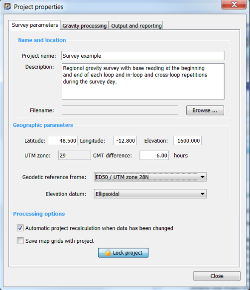
Project name appears in headers of project reports. If filename is not set, Project name is used as the file name.
Free form text describing the project. Optional. Project description does not appear in reports.
Path and file name of the project file. Project is saved in a single file with extension ".fsp". If filename is not set, project name is used when the project is saved for the first time.
Approximate geographic coordinates of the project. These coordinates are used to determine project UTM zone and possible geodetic reference frames. When changed, check geodetic reference frame settings as well.
Positive value of latitude represents Northern hemisphere and positive value of longitude represent Eastern hemisphere.
Under normal circumstances, project coordinates are set after new project is created and there is no need for later changes.
It is not necessary to set coordinates if gravity data are imported from the Scintrex CG-3/CG-5 instrument dump. If coordinates are not set at the moment of import, survey coordinates from the gravimeter are used.
Difference of local time zone from GMT. Positive value means Eastward shift.
All time related data are saved in GMT in the software database. GMT difference value is used to convert data in tables and reports. When editing data, local time is converted to GMT seamlessly.
| Caution | |
|---|---|
Data imported from CG-3/CG-5 dump are converted according to GMT_DIFF header parameter. Please note that CG-3/CG-5 dump GMT_DIFF parameter has opposite sign, i.e. GMT_DIFF is increasing westards! |
List of available geodetic reference frames for the project area. Project area is determined by the project coordinates - see above. Each referencing system is presented by a geodetic datum and projection in the form "Datum / Projection".
All geographic coordinates, i.e. Latitude and Longitude for a given project presented in tables and reports are referenced to the project's geodetic datum. Projected coordinates, i.e. Easting and Northing are referenced to the project's projection based on the selected datum.
All project's maps are plotted in the project's projection with respect to the selected geodetic datum.
When importing stations data, all imported coordinates are expected to be referenced to the project's geodetic datum.
Internally, all coordinates are saved in the BlueWhaleProcessing project database referenced to the WGS-84 datum and necessary conversions are performed where needed.
Geodetic reference frame can be changed at any time. Change of the reference frame does not influence any data in the BlueWhaleProcessing project database.
At present, three options are available for elevations referencing:
Elevation above reference ellipsoid.
Elevation above the EGM-84 (EGM-180) geoid. Use of this elevation datum is deprecated and will be removed from future versions of the software.
Elevation above EGM-96 geoid. Recommended industry standard setting for gravity processing.
All elevation values in tables and reports are presented referenced to the project's elevation datum. When importing data, elevations are expected to be referenced to the project's elevation datum as well.
Internally, all elevations are saved in the BlueWhaleProcessing database referenced to the ellipsoid. Necessary conversions take place where needed.
When checked, any change in project data causes automatic recalculation of the
project. When not checked, project is recalculated by pressing
 Recalculate
button at the toolbar.
Recalculate
button at the toolbar.
Turning automatic recalculation off can help if lot of data editing should be done on a slow computer. Avoiding recalculation while editing can speed up program responses.
 Green/blue badge overlay is displayed over the project icon when automatic
recalculation is turned off.
Green/blue badge overlay is displayed over the project icon when automatic
recalculation is turned off.
| Note | |
|---|---|
If project data are not recalculated automatically, information in reports and maps can be inconsistent. It is recommended to keep automatic recalculation checked as much as possible. |
By default, map grids are not saved in the project database. Each time the map is opened, data are regridded with the use of grid parameters saved with the project.
With the option checked, grid data are saved in the project database. As a result, regridding is not needed when map is opened. On the other hand, project files are significantly bigger with grids saved and project opening needs significantly more time.
Pressing the button toggles lock/unlock state of the project. When the project
is locked, no modifications of project data can be done. Yellow lock overlay
 is displayed over the project icon when the project is locked.
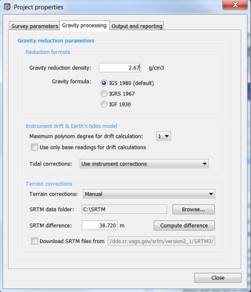
Density used for gravity reductions computation expressed in g.cm -3.
After reduction density change, all existing terrain corrections are automatically recomputed by the formula
 | (2.1) |
where d old represents old density, d new new density after change, t old terrain correction before density change and t new terrain correction after density change.
Formula used for gravity reductions. Choice from three formulas is available:
IGS 1980 (default value)
IGRS 1967
IGF 1930 (not recommended for most applications)
Mathematical expressions and references for particular formulas can be found in the Processing formulas section.
Polynomial model used to determine instrument drift with root mean squares method. 1-st order degree means linear drift model. Linear model is suitable for regional projects with low number of repetitions in every loop. To achieve maximum precision in microgravity projects with repeats every 2 hours or even more frequently, higher order polynom degree can be used to eliminate long period effects like temperature changes, residual tides etc.
Normally, all in-loop repeats are used for instrument drift model assessment. When this box is checked, non-base repeats are excluded from drift model calculation. It can be useful when non-base repeats are lower quality than base readings. It can happen e.g. when reading time is significantly shorter at regular stations than at bases.
Five options are available for selection of the tidal potential model computed with the use of spherical harmonical time/space development:
Use instrument corrections
Using of built-in tidal formula in the instrument. This option is not recommended for microgravity and high-precision surveys. Built-in formula can differ from the real tidal values for more than 0.005 mGal under some circumstances.
Tamura 1987 model (1200 waves)
Buellesfeld 1985 model (656 waves)
Cartwright-Taylor-Eden 1973 model (505 waves)
Doodson 1921 model (378 waves)
Difference between satellite-based models, 1987 and 1985 is less than 0.001 mGal and from the gravimetry point of view can be considered identical.
Descriptions and references concerning the presented tidal models can be found in the Processing formulas section.
Following options control terrain corrections computation for the project:
Not computed
Terrain corrections and complete Bouguer anomalies are not computed. If terrain corrections or complete Bouguer anomalies are requested in reports, corresponding value is printed as "n/a".
Hammer
Hammer method is used for terrain corrections computation. When new station is added to a line, terrain correction for the station is computed at the moment of the first project recalculation. More details can be found in the chapter "Processing procedures and formulas".
Prism (Plouff)
Plouff method of terrain modeling is used for terrain corrections computation. When new station is added to a line, terrain correction for the station is computed at the moment of the first project recalculation. More details can be found in the chapter "Processing procedures and formulas".
Manual
If "Manual" option is selected, terrain corrections can be edited in the Line edit window. No computation is performed in BlueWhaleProcessing unless reduction density is changed - see ????.
The "Manual" terrain correction option can be particularly useful in conjunction with project export/import feature for combination of local and regional terrain corrections in the final steps of the project lifecycle:
In the routine daily processing, regional terrain corrections are computed for zones D-M using Hammer method. Local terrain corrections for zones B and C are computed based on operator's in-situ readings (qualified assessment, inclinometer readings, etc.) with the use of external program, e.g. a spreadsheet. ???? can be used for the calculation, of course.
At the final stage of processing when all data are acquired and processed, the whole project is exported to CSV and imported to a spreadsheet program. Regional corrections are summed with spreadsheet-computed local correction and replace the former values. Finally, the spreadsheet is exported back to CSV format, terrain corrections computation method is switched to "Manual" and terrain data are imported back to the project using "Import coordinates" feature. After recalculation, complete terrain corrections and complete Bouguer anomalies are available.
| Tip | |
|---|---|
If complete recomputation of all terrain corrections is needed, following procedure can be used:
|
| Caution | |
|---|---|
Terrain corrections module is under strong development at present. Its properties and behavior can change in future versions of the software. |
Difference between SRTM3 data and vertical datum used in the project for stations elevations. SRTM3 data can have significant systematic vertical shift as high as up to 15 meters in some areas. This value can correct the shift.
"Compute difference" button can be used to assess the value of SRTM difference. When pressed, project recomputation is started. For each station, approximate elevation is computed with the use of bilinear interpolation from the four closest SRTM3 readings. Average of differences between interpolated and real station elevation over all stations in the project is computed and set as new SRTM difference value.
When checked, SRTM3 data are downloaded automatically from the presented address. When not checked or the presented address is not a valid global SRTM3 data folder, or download failed for any reason, terrain correction for an affected station is computed using available terrain data only.
If some terrain data are missing, progress information in the progress bar is printed in red. New context menu item "Missing SRTM data" appears for project node making a list of missing files.
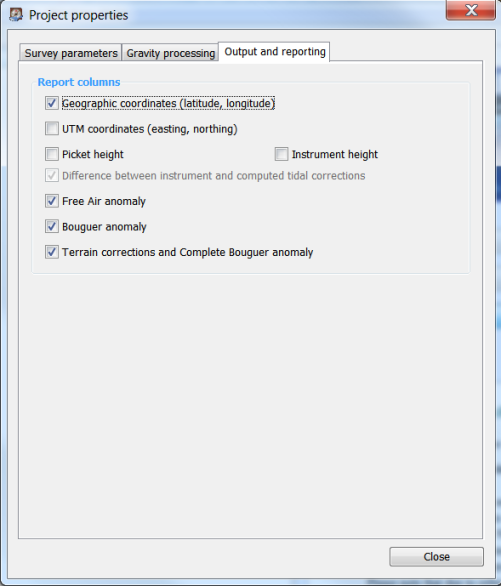
If checked, geographic coordinates are presented in reports.
If not checked (default), UTM coordinates are not presented in reports.
Check if you want to present station picket height in reports.
Check if you want to present instrument height of each gravity reading in reports.
If checked, instrument tidal correction is presented in parenthesis after the correction computed by the software. In addition, if the difference exceeds 0.002 mGal, tidal correction values are printed in blue and if the difference exceeds 0.005 mGal, the difference is printed in red.
Big difference between instrument and computed tidal correction most often means discrepancy in instrument time/GMT difference setting while acquiring the data, or incorrect survey coordinates in the instrument.
If checked, free air anomalies are presented in reports for each station.
If checked, Bouguer anomalies are presented in reports for each station.
If checked, Complete Bouguer anomalies, i.e. anomalies containing terrain corrections, are presented in reports for each station. If terrain corrections are not computed, "n/a" is printed instead.
| | ||
| 2.2. Components of the project | Chapter 3. Processing gravity loops |